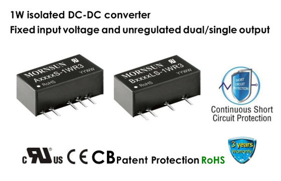

1W isolated DC-DC converter Fixed input voltage and unregulated dual/single output
Description
A05_S-1WR3 & B05_LS-1WR3 series are specially designed for applications where an isolated (two isolated)voltage is required in a distributed power supply system.They are suitable for:pure digital circuits,low frequency analog circuits,relay-driven circuits and data switching circuits.
FEATURES
Continuous short-circuit protection
No-load input current as low as 5mA
Operating temperature range: -40℃ to +105℃
High efficiency up to 85%
I/O isolation test voltage 1.5k VDC
Industry standard pin-out
SIP package
IEC62368, UL62368, EN62368 approved
Specifications
| Selection Guide | ||||||
|
Certification |
Part No. |
Input Voltage(VDC) | Output |
Full Load Efficiency(%) Min./Typ. |
Capacitive Load(µF)* Max. | |
| Nominal (Range) | Voltage (VDC) | Current(mA) Max./Min. | ||||
| CE | A0503S-1WR3 |
5 (4.5-5.5) |
±3.3 | ±152/±15 | 70/74 | 1200 |
|
UL/CE/CB |
A0505S-1WR3 | ±5 | ±100/±10 | 78/82 | 1200 | |
| A0509S-1WR3 | ±9 | ±56/±6 | 79/83 | 470 | ||
| A0512S-1WR3 | ±12 | ±42/±5 | 79/83 | 220 | ||
| A0515S-1WR3 | ±15 | ±34/±4 | 79/83 | 220 | ||
| A0524S-1WR3 | ±24 | ±21/±3 | 81/85 | 100 | ||
| B0503LS-1WR3 | 3.3 | 303/30 | 70/74 | 2400 | ||
| B0505LS-1WR3 | 5 | 200/20 | 78/82 | 2400 | ||
| B0509LS-1WR3 | 9 | 111/12 | 79/83 | 1000 | ||
| B0512LS-1WR3 | 12 | 84/9 | 79/83 | 560 | ||
| B0515LS-1WR3 | 15 | 67/7 | 79/83 | 560 | ||
| B0524LS-1WR3 | 24 | 42/4 | 81/85 | 220 | ||
| Note: *The specified maximum capacitive load for positive and negative output is identical. | ||||||
| Input Specifications | |||||
| Item | Operating Conditions | Min. | Typ. | Max. | Unit |
|
Current (full load / no-load) |
3.3VDC/5VDC output | -- | 270/5 | 286/10 |
mA |
| 9VDC/12VDC output | -- | 241/12 | 254/20 | ||
| 15VDC/24VDC output | -- | 241/18 | 254/30 | ||
| Reflected Ripple Current* | -- | 15 | -- | ||
| Surge Voltage (1sec. max.) | 5VDC input | -0.7 | -- | 9 | VDC |
| Input Filter | Capacitance filter | ||||
| Hot Plug | Unavailable | ||||
| Note: * Refer to DC-DC Converter Application Notes for detailed description of reflected ripple current test method. | |||||
| Output Specifications | ||||||
| Item | Operating Conditions | Min. | Typ. | Max. | Unit | |
| Voltage Accuracy | See output regulation curve(Fig. 1) | |||||
| Linear Regulation | Input voltage change: ±1% | 3.3VDC output | -- | -- | 1.5 | % |
| Others | -- | -- | 1.2 | |||
|
Load Regulation |
10%-100% load |
3.3VDC output | -- | 15 | 20 |
% |
| 5VDC output | -- | 10 | 15 | |||
| 9VDC output | -- | 8 | 10 | |||
| 12VDC output | -- | 7 | 10 | |||
| 15VDC output | -- | 6 | 10 | |||
| 24VDC output | -- | 5 | 10 | |||
| Ripple & Noise* |
20MHz bandwidth |
Others | -- | 30 | 75 | mVp-p |
| 24VDC output | -- | 50 | 100 | |||
| Temperature Coefficient | 100% load | -- | ±0.02 | -- | %/℃ | |
| Short-circuit Protection | Continuous, self-recovery | |||||
| Note: * The “parallel cable” method is used for Ripple and Noise test, please refer to DC-DC Converter Application Notes for specific information. | ||||||
| Mechanical Specifications | |
| Case Material | Black plastic; fiame-retardant and heat-resistant (UL94 V-0) |
| Dimensions | 19.65 x 6.00 x 10.16mm |
| Weight | 2.1g(Typ.) |
| Cooling Method | Free air convection |
![]()